In electrical substations, proper earthing is critical for ensuring safety, protecting equipment, and maintaining operational reliability. One advanced method is reinforcement earthing or so-called rebar earthing, a practice that involves integrating the structural components of buildings, foundations, and equipment into the earthing system. This approach not only improves the overall efficiency of the grounding system but also reduces installation costs by utilizing existing structural elements.
What is Reinforcement Earthing?
Reinforcement earthing leverages the structural components of a substation—such as building columns, beams, slabs, and foundations—for earthing purposes. By electrically bonding these structures to the earthing grid, they become part of a robust and low-resistance grounding network.
This method is especially effective in high-voltage substations and areas prone to high fault currents, where traditional earthing systems may be insufficient.
Why Reinforcement Earthing Matters
The need for reinforcement earthing stems from the dual challenges of safety and reliability. Substations manage high fault currents during equipment faults or lightning strikes. Without an effective grounding system, these currents can damage equipment, jeopardize personnel safety, and create operational hazards. Reinforcement earthing addresses these challenges by providing multiple low-resistance paths for fault currents.
In addition to safety, reinforcement earthing enhances operational reliability. By utilizing structural elements already present in the substation, it ensures better potential equalization and fault current dissipation. This reduces the risk of voltage surges affecting critical equipment and minimizes downtime.
Key Applications of Reinforcement Earthing
Reinforcement earthing is implemented in several critical areas of a substation, ensuring a comprehensive grounding system that enhances both safety and reliability:
Building Columns and Beams
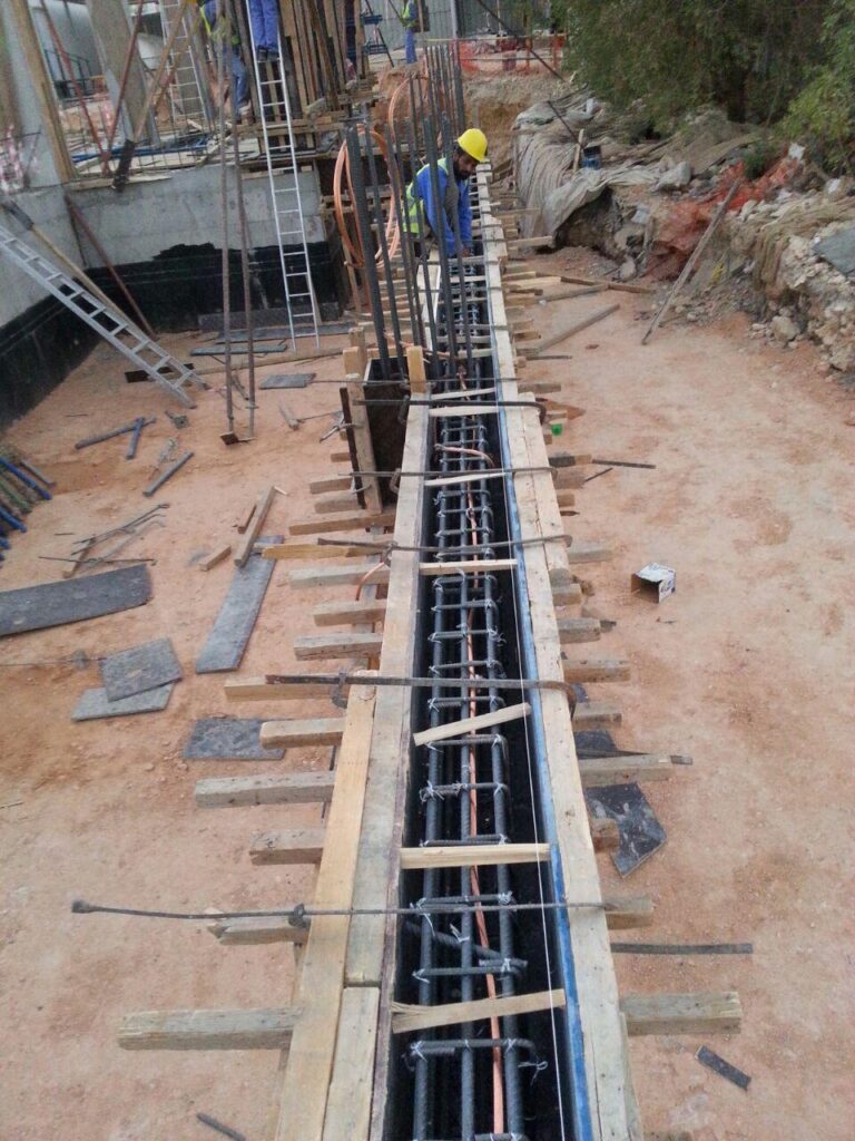
Reinforced concrete columns and beams are integral to substation design. The steel reinforcements (rebars) within these structures are electrically bonded to create a continuous conductive path. When connected to the earthing system, these components provide reliable fault current dissipation and minimize ground potential rise. Figure 1 below demonstrates beam earthing using a bare copper conductor (120 mm²) tied to the rebars with clamps and rising to the column.
Slabs and Floors
Concrete slabs and floors, containing interconnected steel reinforcements, are excellent candidates for reinforcement earthing. Proper bonding of these rebars ensures uniform potential distribution across the substation, reducing step and touch voltages to safe levels.
Transformer Foundations
The foundation of a transformer, which supports heavy electrical loads, is a critical point for grounding. By embedding earthing conductors within the foundation during construction, a low-resistance path is created for fault currents, protecting the transformer and associated equipment from potential damage.
Equipment Foundations
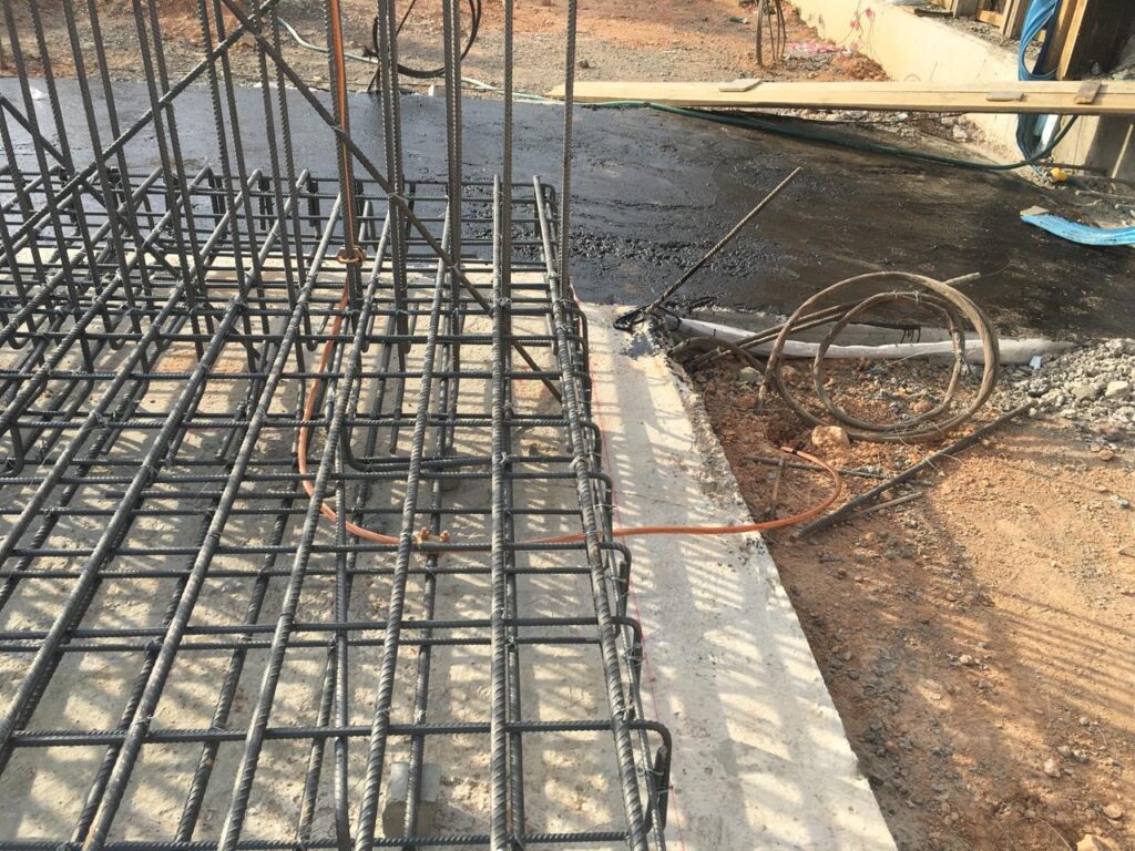
Foundations for heavy electrical equipment, such as circuit breakers and switchgear, can be seamlessly integrated into the earthing system and the main grounding grid. This ensures that fault currents are safely directed into the ground, enhancing both safety and operational reliability. Figure 2 below illustrates a real-world example of foundation earthing connected to the main grid.
Interconnection Between Structures
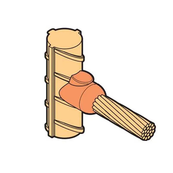
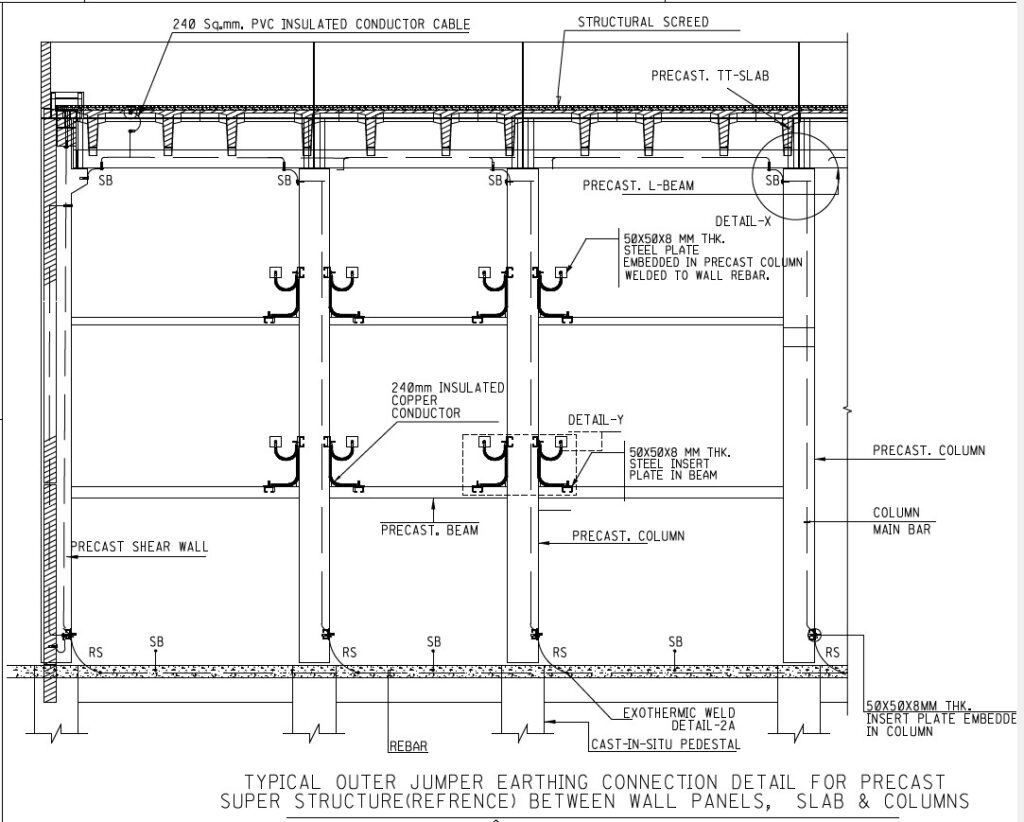
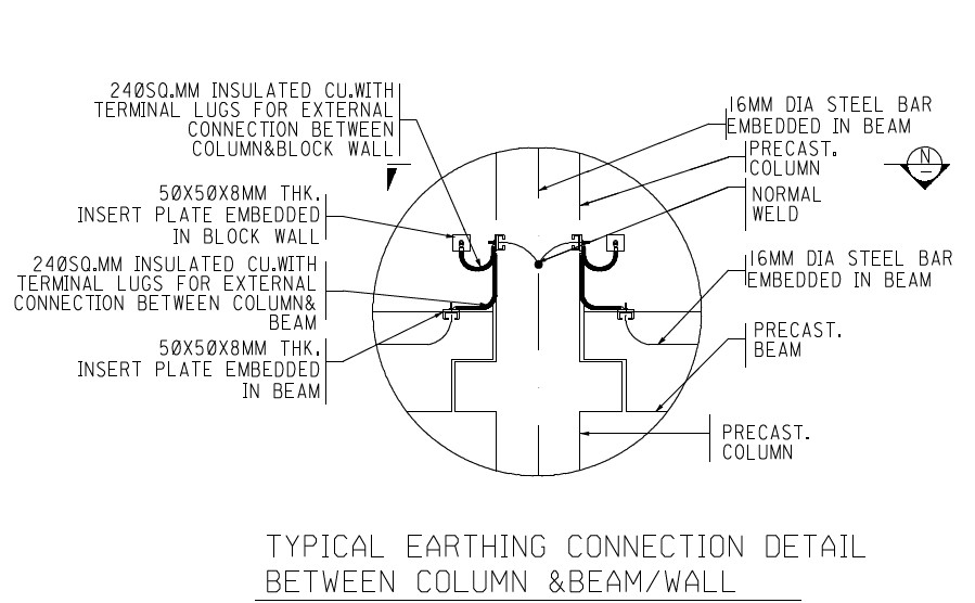
The continuity of the grounding system relies heavily on the interconnection between structural elements such as walls, beams, and columns. Properly designed interconnections ensure that rebars within these components are electrically bonded, creating a unified conductive network. This design guarantees the consistent dissipation of fault currents throughout the structure and eliminates potential differences that could pose safety risks. A well-planned interconnection system enhances the overall grounding effectiveness of the building. Figure 3 shows a design snapshot highlighting the interconnection between walls, beams, and columns.
The Installation Process
The installation of reinforcement earthing begins with assessing the substation’s structural components. Identifying elements like columns, beams, and slabs that can be integrated into the earthing system is crucial. Once identified, the rebars within these components must be electrically bonded to ensure continuity. This is typically achieved using welding or clamps, with exothermic welding (cadwelding) being the preferred method due to its durability and resistance to corrosion. The reinforcement earthing drawing shall be checked in conjunction with Substation Main Grid drawing and Equipment Earthing drawing.
After bonding the rebars, the next step involves connecting them to the earthing mesh grid. Conductors made of copper-clad steel or pure copper are used to link the structural elements to the grid. Connections should be direct and redundant, ensuring multiple paths for fault currents. For transformer and equipment foundations, earthing conductors should be installed within the concrete before pouring, creating a permanent bond with the structure.
Corrosion protection is an essential aspect of the installation process. Exposed parts of the connections must be treated with anti-corrosion coatings, and materials such as stainless steel clamps or tinned copper conductors are recommended for long-term durability. Finally, inspection and testing ensure the effectiveness of the installed system. Tests for electrical continuity and resistance help verify that the system meets design specifications and regulatory standards.
Key Benefits of Reinforcement Earthing
Reinforcement earthing offers several benefits that make it indispensable in substation design. It enhances safety by reducing step and touch voltages, ensuring personnel protection. Operational reliability improves as the system efficiently handles fault currents and prevents equipment damage. Additionally, using structural components reduces installation costs and optimizes space, which is particularly advantageous in compact substations.
Moreover, reinforcement earthing supports lightning protection. Structural elements, when properly bonded, act as natural conduits for lightning currents, safely dissipating them into the ground. This integration not only simplifies the lightning protection system but also ensures its effectiveness.
Challenges and Considerations
Despite its advantages, reinforcement earthing presents certain challenges:
- Corrosion Risk: Environments with high moisture or salinity can accelerate corrosion, requiring additional protective measures.
- Electrical Continuity: Ensuring the continuity of rebars across large structures can be challenging and demands meticulous planning during construction.
- Soil Resistivity: High-resistivity soils may necessitate chemical enhancements to improve conductivity.
- Testing Accessibility: Buried connections and structural elements are not always easily accessible, complicating regular inspection and testing.
These challenges can be addressed through meticulous planning, proper material selection, and adherence to international standards such as IEEE 80 and IEC 60364.
Additional Resources
To learn more about specialized earthing materials and protection solutions, you can refer to the Bahra Earthing Catalogue. This catalogue provides detailed information on high-quality earthing products and techniques.
Conclusion
Reinforcement earthing is a cornerstone of modern substation design, offering a reliable, cost-effective, and space-efficient solution for grounding. By integrating structural elements such as columns, beams, slabs, transformer foundations, and equipment foundations, it creates a robust system capable of handling high fault currents and lightning strikes. Proper planning, installation, and maintenance ensure the system’s long-term performance and compliance with safety standards.
Including real-world examples, such as photos of beam earthing and foundation earthing, along with design snapshots, can further illustrate the effectiveness and practical implementation of reinforcement earthing. As substations evolve to handle increasing power demands, reinforcement earthing remains essential for ensuring safety, reliability, and operational efficiency.
- Cost Efficiency
- By utilizing existing structures, reinforcement earthing reduces the need for additional earthing conductors and electrodes.
- Enhanced Safety
- Structural components provide multiple low-resistance paths for fault currents, reducing step and touch voltages.
- Improved Reliability
- A reinforced earthing system ensures better fault current dissipation and minimizes potential rise during faults.
- Space Optimization
- In compact substations, using structural elements for earthing saves space compared to installing separate grounding electrodes.
Installation Process for Reinforcement Earthing
Advantages of Using Structural Components for Earthing
- Connection to the Earthing Mesh Grid
- Run conductors from the structural components to the mesh grid using copper-clad steel or pure copper cables.
- Ensure that connections are direct and provide multiple paths to the earthing grid for redundancy.
- Integration with Transformer and Equipment Foundations
- Install earthing conductors in the concrete before pouring. This ensures a permanent bond between the foundation and the earthing system.
- For transformer foundations, connect the base plates to the grounding grid using flat copper strips or conductors.
- Lightning Protection Integration
- Structural elements can act as natural down conductors for lightning currents. Bond them to the earthing grid to complete the lightning protection system.
- Corrosion Protection
- Apply anti-corrosion coatings to exposed parts of the connections and use corrosion-resistant materials like stainless steel clamps or tinned copper conductors.
- Testing and Verification
- Perform continuity and resistance tests to verify the effectiveness of all connections.
- Ensure that the overall system resistance meets design requirements (typically <1 ohm in substations).
Best Practices for Reinforcement Earthing
- Ensure Continuity of Rebars
- During construction, confirm that all rebars in columns, beams, and slabs are electrically connected to form a continuous conductive path.
- Multiple Bonding Points
- For large structural elements, provide multiple connections to the earthing grid to enhance fault current dissipation.
- Compliance with Standards
- Follow standards such as IEEE 80 and IEC 60364 for designing and implementing the earthing system.
- Periodic Inspection
- Inspect and test the earthing system regularly to ensure long-term performance and safety.
- Integration with Equipment Earthing
- Ensure that structural components are seamlessly integrated with the earthing of electrical equipment for a unified grounding system.
Challenges in Reinforcement Earthing
- Corrosion Risk
- Structural components may be exposed to moisture, requiring additional protection to prevent corrosion.
- Electrical Continuity
- Ensuring the continuity of rebars across large structures can be challenging and requires careful attention during construction.
- Soil Resistivity
- High-resistivity soil can limit the effectiveness of reinforcement earthing, necessitating the use of chemical enhancements.
- Testing Accessibility
- Testing the integrity of buried connections and rebars can be difficult after installation.
Conclusion
Reinforcement earthing is a powerful and cost-effective technique for improving the safety and reliability of electrical substations. By integrating building columns, beams, slabs, transformer foundations, and equipment foundations into the earthing system, substations can achieve a low-resistance grounding network that effectively handles fault currents, minimizes risks, and ensures operational continuity.
Careful design, installation, and regular testing are essential to maximize the benefits of reinforcement earthing and ensure long-term performance. As substations evolve to meet increasing power demands, reinforcement earthing remains a cornerstone of safe and efficient operations.